
Blog
Micro-Soldering Tools and iPhone Motherboard Repair: A Complete Guide

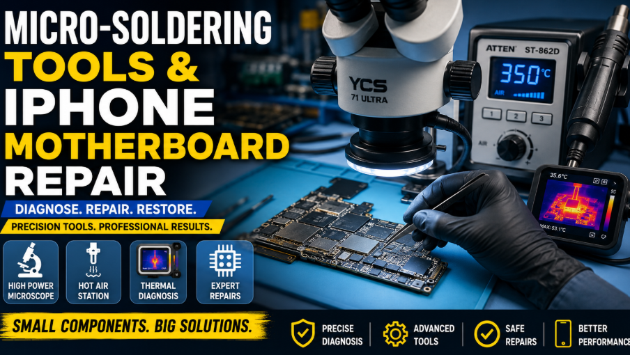
Modern iPhones are built with tightly packed components, layered circuit boards, and highly sensitive power and data lines. This compact design makes the devices fast and efficient, but it also makes motherboard repair more challenging than ordinary screen, battery, or charging-port replacement. When an iPhone has no power, suffers from random restarts, fails to charge, loses touch response, or shows signs of water damage, the problem may be located deep inside the logic board. In such cases, micro-soldering becomes an essential repair skill.
Micro-soldering is the process of diagnosing and repairing extremely small electronic components under magnification. It requires the right tools, steady hand control, technical knowledge, patience, and a clean working environment. A technician may need to remove damaged chips, rebuild broken pads, replace filters or capacitors, repair torn traces, or reball integrated circuits. These jobs cannot be completed safely with ordinary phone repair tools.
This guide explains the main tools used in micro-soldering, the basic process of iPhone motherboard diagnosis, and the safety practices that help technicians perform reliable board-level repairs.
Understanding iPhone Motherboard Repair
The iPhone motherboard, also known as the logic board, controls almost every function of the device. It manages power, charging, display output, touch response, audio, cameras, wireless communication, storage, and data processing. A fault in one small component can affect an entire section of the phone.
For example, a shorted capacitor on a main power rail may stop the phone from turning on. A damaged charging IC can prevent the battery from receiving power. Corrosion around a connector may cause camera, touch, or display problems. Broken solder joints under a chip may lead to boot loops, signal loss, or intermittent faults.
Motherboard repair begins with diagnosis. A technician must understand the symptoms, inspect the board, test important lines, compare readings, and identify the exact area of failure. Replacing components without proper testing can waste time and may create additional damage.
Successful repair depends on three main abilities: seeing small components clearly, applying controlled heat, and measuring electrical behavior accurately. This is why a microscope, hot air station, multimeter, soldering iron, and fault detection equipment are central to a professional micro-soldering setup.
Why Magnification Is Essential
Most motherboard components are too small to inspect with the naked eye. Tiny resistors, capacitors, filters, coils, and IC pins may appear normal without magnification even when they are cracked, corroded, shifted, or poorly soldered.
A high-quality Microscope for Phone Soldering gives the technician a clear and enlarged view of the work area. It helps with fault inspection, component alignment, solder joint examination, jumper wire placement, and pad repair.
For phone motherboard work, a trinocular microscope can be especially useful because it supports direct viewing as well as camera output. Technicians can record repairs, train team members, or display the repair area on a monitor. Good working distance is equally important. There should be enough space between the lens and motherboard for tweezers, soldering tips, hot air nozzles, and other tools.
Clear magnification reduces the risk of mistakes. It helps the technician notice lifted pads, solder bridges, cracked joints, hidden corrosion, and misaligned components before power is applied to the board. Proper lighting around the microscope also improves visibility and reduces eye strain during long repair sessions.
Choosing a Reliable Hot Air Station
A hot air station is used to heat and remove surface-mounted components without touching every solder joint individually. It is particularly important for IC replacement, connector removal, shielding work, reflow procedures, and reballing preparation.
The ATTEN ST-862D hot air station can be used for controlled heating and desoldering tasks. Stable airflow and accurate temperature control are important because excessive heat can damage nearby components, warp the board, lift pads, or weaken internal motherboard layers.
Different repair jobs require different nozzle sizes, airflow levels, and temperature settings. A small component usually needs a focused nozzle and moderate airflow. A larger integrated circuit may require broader heat distribution and more heating time.
The goal is not to apply the highest possible temperature. The objective is to heat the solder evenly while protecting the surrounding area. Excessive airflow may blow tiny components away, while insufficient heat may cause a technician to pull on a component before the solder has fully melted.
Technicians should preheat the work area when appropriate, apply suitable flux, monitor component movement, and avoid keeping the nozzle in one position for too long. Sensitive plastic connectors, cameras, microphones, and nearby chips should be protected with heat-resistant tape or shielding material.
Controlled hot air work takes practice. Beginners should train on scrap boards before attempting repairs on expensive iPhones. Learning how solder reacts under heat is one of the most important parts of micro-soldering.
The Role of a Precision Soldering Iron
A precision soldering iron is used for tasks that require direct contact. These include removing small components, rebuilding pads, installing jumper wires, cleaning solder, and touching up joints after hot air work.
The soldering tip should match the size of the repair. A tip that is too large may damage nearby components, while a tip that is too small may transfer heat poorly. Fine conical, bent, or knife-shaped tips are commonly used for phone motherboard repairs.
Temperature control is essential. If the iron is too cold, the solder will not flow properly and may create weak joints. If it is too hot, pads can lift and board material can burn. Fresh solder, quality flux, and a properly cleaned tip help transfer heat efficiently.
A technician should never press hard on the motherboard. Soldering depends on heat transfer, not physical force. Gentle contact and short working times are safer than prolonged pressure.
The tip should also be cleaned regularly. Oxidized or contaminated tips transfer heat poorly and make precise work more difficult. A brass tip cleaner or suitable cleaning sponge can help maintain the tip without causing unnecessary wear.
Using a Multimeter for Fault Diagnosis
A multimeter is one of the most important diagnostic tools in iPhone motherboard repair. It can measure voltage, resistance, continuity, and diode values. These readings help the technician understand whether a circuit is open, shorted, or behaving normally.
Diode mode is commonly used to compare readings on connectors and power lines. If a line gives a very low reading or shows continuity to ground, it may have a short circuit. However, not every low reading indicates a fault. Some lines naturally have low resistance, so technicians should compare measurements with a known-good board, schematic, boardview, or reliable reference data.
Voltage measurements are useful when the board is powered. They can confirm whether important power rails are being generated. If a rail is missing, the technician can trace backward through the circuit to identify the controlling IC, enable signal, coil, filter, or shorted component.
Resistance mode can help locate abnormal electrical loads. Continuity testing is useful for checking broken traces, damaged connectors, and completed jumper wire repairs.
Before measuring, the technician should place the motherboard securely, select the correct meter mode, and use sharp probes. Slipping probes can connect two points accidentally and damage the board.
Finding Short Circuits with Thermal Imaging
Short circuits are common in water-damaged, dropped, or previously repaired iPhones. A shorted component may draw excessive current and heat up when power is applied. Finding that component can be difficult because the motherboard contains hundreds of tiny parts.
A phone pcb fault diagnosis Tool can help identify unusual heat patterns on the board. Thermal imaging allows the technician to observe which component or area becomes warm first when controlled voltage is injected into a shorted line.
This method can save time compared with removing or testing every capacitor individually. However, voltage injection must be performed carefully. The technician should understand the expected voltage of the circuit and begin with a low, current-limited supply. Injecting too much voltage can destroy chips that were originally working correctly.
Thermal imaging is most effective when combined with schematic knowledge and multimeter readings. The multimeter confirms the short, the schematic identifies the affected circuit, and the thermal camera helps locate the heating component.
Other short-detection methods include freeze spray and high-purity isopropyl alcohol. A heating component may melt frost or evaporate alcohol faster than the surrounding area. These methods are useful, but thermal imaging often provides a clearer and faster view of the affected section.
The Importance of Schematics and Boardviews
Micro-soldering is not only about removing and replacing components. A technician must understand how the circuit works. Schematics show electrical connections, component values, power rails, signals, and control lines. Boardviews show the physical position of components on the motherboard.
When an iPhone does not power on, the technician can use a schematic to follow the boot sequence. The process may involve checking battery voltage, main power rails, charging communication, CPU-related supplies, clock signals, and enable lines.
If a display has no image, the technician may check display power rails, filters, connector pins, backlight circuits, and data lines. For charging problems, the technician may inspect USB communication, charging control, battery sensing, and power management sections.
Without a schematic, repair work can turn into guesswork. With a schematic and boardview, diagnosis becomes systematic. Technicians can follow the affected line, identify connected components, and test each stage logically.
Preparing the Motherboard for Repair
Before applying heat, the motherboard should be inspected and cleaned. Shields may need to be removed to access the affected area. Any adhesive, dust, corrosion, or residue should be cleared carefully.
The battery must be disconnected before board-level work begins. Cameras, display assemblies, and other sensitive modules should also be removed when necessary. The motherboard should be placed in a stable holder so it cannot move during soldering.
Flux should be applied in a controlled amount. It improves solder flow, reduces oxidation, and helps heat spread evenly. Too much flux can make the work area difficult to see and clean, while too little flux can create dry or uneven solder joints.
Nearby components should be protected before heating. Heat-resistant tape, metal shields, or other temperature-resistant materials can reduce the risk of accidental component movement.
The technician should also study the area before beginning. Understanding where components are located and which parts are sensitive can prevent avoidable damage.
Removing and Replacing Small Components
Small passive components such as resistors, capacitors, coils, filters, and diodes can often be removed with a soldering iron or hot air.
The damaged component should first be identified by its board position and electrical value. Before removal, the technician should confirm that the replacement part is correct. Components that look identical may perform completely different functions or have different values.
Flux is applied around the component, and controlled heat is added until the solder melts. The part is then lifted gently with fine tweezers. It should never be forced from the board.
The pads are cleaned with solder wick, fresh solder, and flux. During cleaning, the technician must avoid excessive pressure because motherboard pads can lift easily.
The replacement component must be aligned accurately. Even slight misalignment can create poor contact or a solder bridge between pads. After soldering, the area should be inspected under the microscope and tested with a multimeter before powering the phone.
IC Removal, Reballing, and Replacement
Integrated circuits are more difficult to replace because they may have many solder balls hidden underneath. Removing an IC requires even heating and careful lifting. Pulling the chip before the solder is fully melted can tear pads from the board.
After removal, the pads are cleaned and inspected. If the original chip will be reused, old solder is removed and new solder balls are applied using an appropriate stencil. This process is called reballing.
Reballing requires accurate alignment, correct ball size, controlled heat, and clean surfaces. The reballed chip is positioned on the motherboard and heated until the solder balls connect evenly with the pads.
Some ICs are paired or programmed specifically for the device. Replacing them without transferring their data may cause the phone to lose important functions. Technicians must understand which chips can be replaced directly and which require programming, data transfer, or paired component work.
Heat distribution is especially important during IC replacement. Uneven heating may cause the chip to sit incorrectly or produce weak connections underneath. The technician should observe the chip carefully and allow it to settle naturally as the solder melts.
Repairing Lifted Pads and Broken Traces
Excessive heat, force, corrosion, or poor previous repair attempts can damage motherboard pads and traces. A lifted pad means the copper connection has separated from the board. A broken trace interrupts the electrical path between components.
These faults can sometimes be repaired using very thin jumper wire. The technician identifies the destination of the damaged connection through a schematic or boardview. A small area of the connected trace may be exposed, cleaned, tinned, and joined with wire.
The jumper should be routed carefully so that it does not interfere with shields, connectors, or nearby components. It must also be thin enough to fit safely inside the assembled phone.
After electrical testing, UV solder mask can be applied to hold and protect the wire. The mask should be cured correctly before the motherboard is handled or reassembled.
Pad and trace repair requires excellent microscope control. The repaired connection must be strong enough to survive assembly but delicate enough to avoid damaging the surrounding board.
Water Damage and Corrosion Treatment
Water damage can create short circuits, corrosion, and broken electrical connections. The first step is to disconnect power and inspect the motherboard under magnification.
Corroded areas may appear green, white, black, or dull. Components around connectors, shields, and exposed edges are common failure points. The board can be cleaned with high-purity isopropyl alcohol and a soft ESD-safe brush.
In severe cases, ultrasonic cleaning may be useful, but it must be performed with appropriate equipment and cleaning solution. The motherboard must be dried completely before testing.
Cleaning alone does not guarantee a successful repair. Corrosion may have damaged pads, traces, solder joints, connectors, or components. After cleaning, the board should be tested systematically with a multimeter and power supply.
Powering a wet or heavily corroded board too early may create additional damage. Diagnosis should begin only after the motherboard is dry and visually inspected.
ESD Protection and Workspace Safety
Electrostatic discharge can damage sensitive iPhone components without producing visible signs. Technicians should use an ESD mat, grounded wrist strap, ESD-safe tweezers, and suitable storage trays.
The workspace should have good ventilation because flux fumes and heated materials can irritate the lungs and eyes. A fume extractor is recommended for technicians who perform soldering work regularly.
Protective glasses should be used during soldering, cutting, scraping, and cleaning. Food and drinks should be kept away from the repair area. Tools should be organized so the technician can work without rushing or searching for equipment.
A clean bench reduces contamination and prevents screws, solder balls, wires, or metal pieces from contacting the motherboard. Good lighting and a comfortable working position also improve control during long repair sessions.
Testing After the Repair
A repair should never be considered complete immediately after soldering. The work area must be cleaned, inspected, and tested.
First, the technician should check for solder bridges, missing components, loose parts, burned areas, and damaged pads. Multimeter readings should be taken again to confirm that the short circuit or open line has been corrected.
The motherboard can then be connected to a controlled power source. Current draw should be observed during the boot process. Unusual current behavior may indicate that another fault remains.
After the device powers on, all related functions should be tested. A charging repair should include charging speed, cable detection, battery communication, and data connection checks. A display repair should include image, touch response, brightness adjustment, and sensor testing.
The phone should also be tested after full assembly because pressure, shields, cables, screws, and grounding connections can affect motherboard behavior.
Building Professional Micro-Soldering Skills
Micro-soldering takes time to learn. Watching repair demonstrations can help technicians understand techniques, but hands-on practice is essential. Beginners should start with scrap boards and simple tasks such as removing shields, replacing larger components, cleaning pads, and installing jumper wires.
As hand control improves, the technician can move to smaller components, connector replacement, trace repair, reballing, and complex IC work.
It is helpful to document repairs, save multimeter readings, and study failed attempts. Every motherboard teaches something about heat control, diagnosis, component behavior, and repair planning.
A good technician does not rush. The most reliable repairs come from careful observation, logical testing, controlled technique, and patience. Knowing when to stop and inspect the board is just as important as knowing how to apply heat.
Turning Micro-Soldering Knowledge into Reliable Repairs
iPhone motherboard repair is a specialized field that combines electronics knowledge with precise manual work. The quality of the repair depends heavily on the technician’s tools, diagnosis process, and level of control. A clear microscope improves accuracy, a stable hot air station provides safer heat control, and a reliable fault diagnosis system helps locate hidden electrical problems.
The most important principle is to diagnose before replacing parts. Micro-soldering is not guesswork. It is a structured process involving inspection, measurement, circuit analysis, controlled component removal, careful replacement, and complete testing.
With proper equipment, regular practice, and patience, technicians can repair faults that would otherwise require complete motherboard replacement. These skills can save devices, protect customer data, reduce electronic waste, and create valuable opportunities for repair professionals who are willing to develop advanced board-level expertise.

How to Fix “Error Connecting to Server” on WebRTC Video Chats

Scaling Modern Applications: A Guide to Microservices and AWS Expertise

Evaluating a Fast Turn PCB Partner for High-Frequency Applications

Why Roaming Can Be a Problem Abroad and How an eSIM Can Help

Do You Really Need a Watch Winder for Your Automatic Watch?

Why Sportswear Is No Longer Limited to Athletes

The Name Necklace Trend Is Back, But More Grown-Up

A Clearer Route to Reliable professional drain clearance and CCTV inspection

Is The High Street Bank Losing Its Grip On UK Business Loans?

TabooTube Explained: The Powerful Platform for Unfiltered Content

SSIS 469: Fixing SQL Data Errors in ETL Workflows

content://cz.mobilesoft.appblock.fileprovider/cache/blank.html: Explained with Powerful Insights

Scrolller Explained: The Powerful Way to Browse Reddit Images

Zavalio com Explained: The Ultimate Truth You Must Know

adswynk com: Monetize Links With Smart Ads in 2025

Deshoptec com Review: Powerful Truth About This Online Store

kz43x9nnjm65: The Smart Code Transforming Digital Technology

Novafork: The Best Free Streaming Site for Movies, Shows & Anime

Milohacherry Coin Explained: The Powerful Lifestyle Crypto Rewarding Travel & Fitness
-
 Blog10 months ago
TabooTube Explained: The Powerful Platform for Unfiltered Content
-
 Blog12 months ago
SSIS 469: Fixing SQL Data Errors in ETL Workflows
-
 Blogs1 year ago
content://cz.mobilesoft.appblock.fileprovider/cache/blank.html: Explained with Powerful Insights
-
 Blog10 months ago
Scrolller Explained: The Powerful Way to Browse Reddit Images